Posts

Trailer

Image
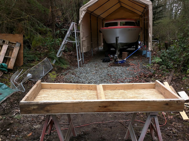
It took some doing, but the trailer is free of the boat. The following steps were involved: 1.      - Lower the trailer tongue to raise the stern 2.      - Build a cradle to support the stern 3.      - Raise the tongue and pull the trailer out from underneath o     tie the transom to a tree conveniently located about 20' behind the boat o     jack up and block the bow of the boat o     slowly pull the boat forward until the bow cribbing meets a trailer crossmember o     repeat until the trailer is about halfway out 4.      Build another cradle a bit aft of amidships o     Repeat above until the trailer is nearly free of the boat 5.      Block up the keel near the bow The numbers and bullets make it sound easy, but it was tedious and a bit nerve-wracking. Here is the story in pictures: ...
Image
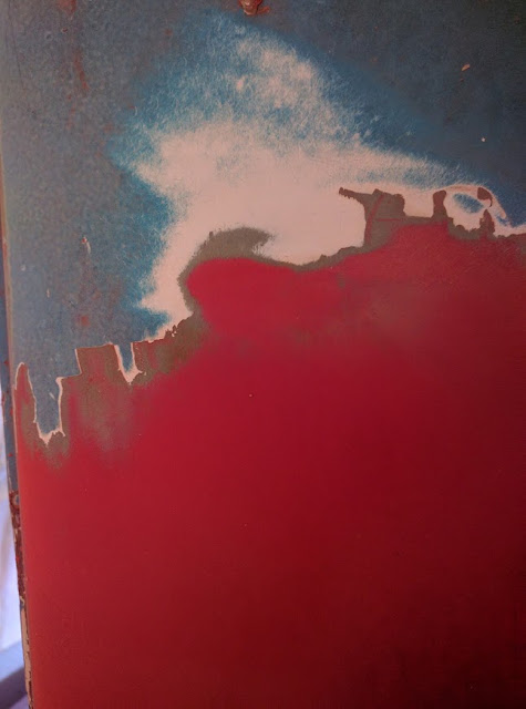
Painting Now that the rebuild of the stern is complete the Offshore is ready to get on the water! Of course it's lacking a motor and looks like crap, but theoretically I could launch and paddle around! At some point I also need to get the boat off the trailer, clean up the latter, and have it inspected by Washington State Patrol so it can be licensed and legal. Haven't figured out the best way to do that, but will soon. Good preparation is the key to a successful paint job, so because the paint is so old it is necessary to strip it all off, down to the gel coat. There were three coats of paint: gray primer, white, then blue on the trim. All of the coats were sprayed, probably using enamel paint. Not having any history of the boat I can only guess this was done in the 80s or maybe earlier, based on the pervasive fading. Partially sanded side deck showing three coats of paint over the original red gel coat. I've been stripping the old paint off the topsides using a...
Image
Splash Well Shelf After completing the transom, the last task for restoring the aft portion of the Offshore was to rebuild the splash well. Most reading this probably know about this feature of outboard boats, but I wasn't real familiar with it. If I understand it correctly, when you slow down, especially coming off a plane, the wake (wave) catches up to the boat and you can get water over the transom. If you don't have a splash well this water would go into the bilge, which you could either pump out or open the drains when the boat is under way to let gravity and vacuum expel it. The well is self draining.  Remnants of the port (top) and starboard splashwell shelf when I got the boat. The shelf rests on cleats installed on the bulkhead and transom. One could also put cleats along the side, but the factory didn't do this; instead they tabbed the shelf onto the bottom of the vertical stiffeners you see in the above pictures. I did the same, because the s...
Image
Miscellaneous  Since the last post I’ve installed flotation and the splash shelf, and am in the processes of finishing it. I’ll post details on this in a week or so. This post will deal with some of other work I’ve been doing, mostly while waiting for epoxy to cure. Tanks One feature of Skagit boats (at least those 20’ and over) I thought was pretty cool were integral fuel tanks constructed of fiberglass. Often referred to as “saddle tanks” because they were located on each side amidships, they offered convenient filling from gas caps located on the side decks. To me they were an attractive feature and I was glad to see they were intact. In the 1950’s fiberglass was becoming known as a miracle material for boat building. It didn’t need an elaborate wooden support system (i.e., keel, ribs, stringers), never rotted, could be constructed quickly and at low cost, and never needed painting. So, why not construct fuel tanks with it? Skagit Plastics did, along wi...
Image
Transom III The new transom, with symmetrical cut-out and holes drilled for motor mount. Since the last post I bonded layers 3 and 4 to the transom! The 3 rd was ¼”, and just slid in behind the shoulder at the aftermost part of the center rib with a gap a bit less than ⅛”. The third ply in place. I later thoroughly filled the gap with GelMagic. The 4 th  and last was the  ½ “ thick plywood, which I cut out to accommodate the knee. I took special care to shape the edges so they fit flush to the curvature of the hull. For this I used a grinder with a 60-grit flapper wheel; it's easy to control and and quickly removes material. Shaping the edge of the last ply. To measure the amount of material to grind off I used a straight edge on a scrap of the appropriate size plywood, and measured the distance between the previous ply and the hull every three vertical inches. With the previous ply template laid on the plywood to be cut, I just added these measurements...